Cold shrink straight Joint installation process
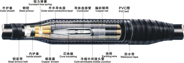
Due to the limited manufacturing length of power cables, a complete power line can only be formed by connecting each power cable to ensure the normal transportation of power, and the insulation performance and core connection effect of the connection between the cable and the cable should not be lower than the cable itself. In this case, it is necessary to use the cable intermediate joint as a connection aid. However, the connection between the cable and the cable does not mean that only the cable intermediate joint is required to connect, and it also requires precise handling during installation. The imprecise installation method is one of the most important reasons for the failure of electric transportation.
Next, I will explain to you how to install the cold-shrinkable power intermediate joint to ensure the most perfect connection of power (complete installation tutorial video is attached below)
1. Preparations before installation:
a: It should be noted that the installation site is free of dust and maintains a dry and ventilated environment.
b: Check whether the installation tools are complete.
c: Check whether the cable accessories match the cable.
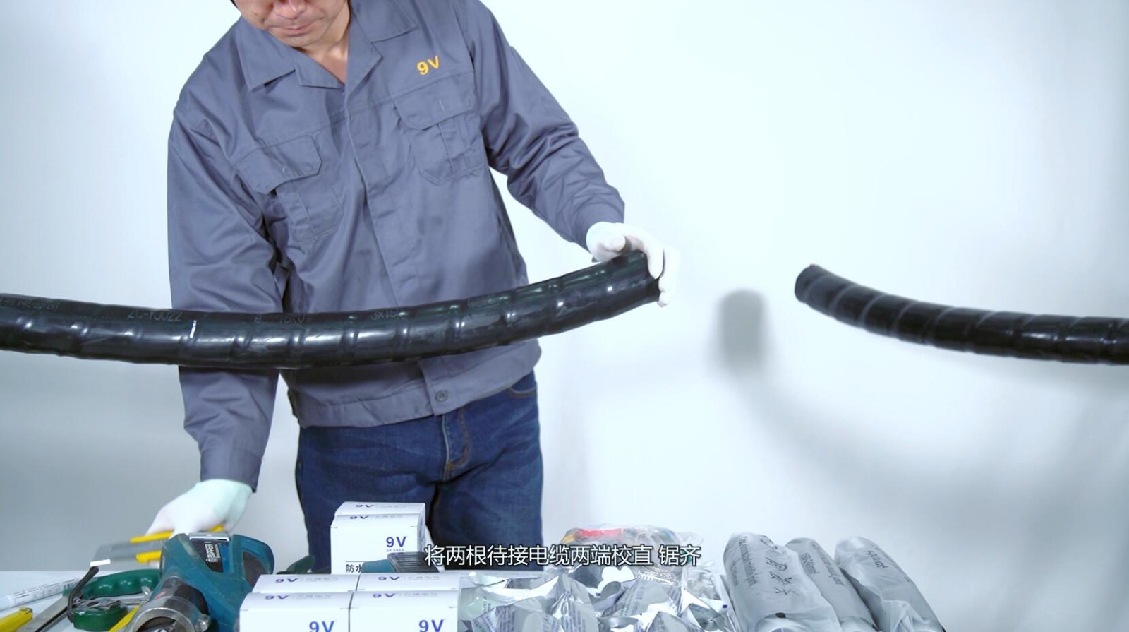
d: Straighten and saw both ends of the two cables to be connected.
2. Stripping
a: Strip according to the size of the installation instructions
b: Peel off the outer sheath in sequence (long end 800mm, short end 600mm), leave (30mm) at both ends of the steel armour and strip off the rest, leave (80mm) at each end of the inner sheath and strip off the rest, and remove the filler (filler) material backup), the three phases are separated.
c: After measuring the length of A+50mm, mark it with PVC, peel off the copper shield, and cut the semi-conductive layer according to the length of the installation manual (Figure 1: A). (Be careful not to damage the insulating layer when stripping the semiconducting layer).
d: The end of the semiconducting layer is chamfered with a tool to make the transition between the semiconducting layer and the insulating layer smooth.
e: Sand the surface of the insulating layer with fine sandpaper. (Be careful not to sand down to the semiconducting layer).
f: Polish the surface of the remaining steel armor and clean the outer sheath.
g: Polish the outer sheath and the inner sheath.
h: Add 3mm to 1/2 the length of the connecting pipe, and cut off the insulating layer. Remove burrs from the ends of the insulation and clean the cable insulation.
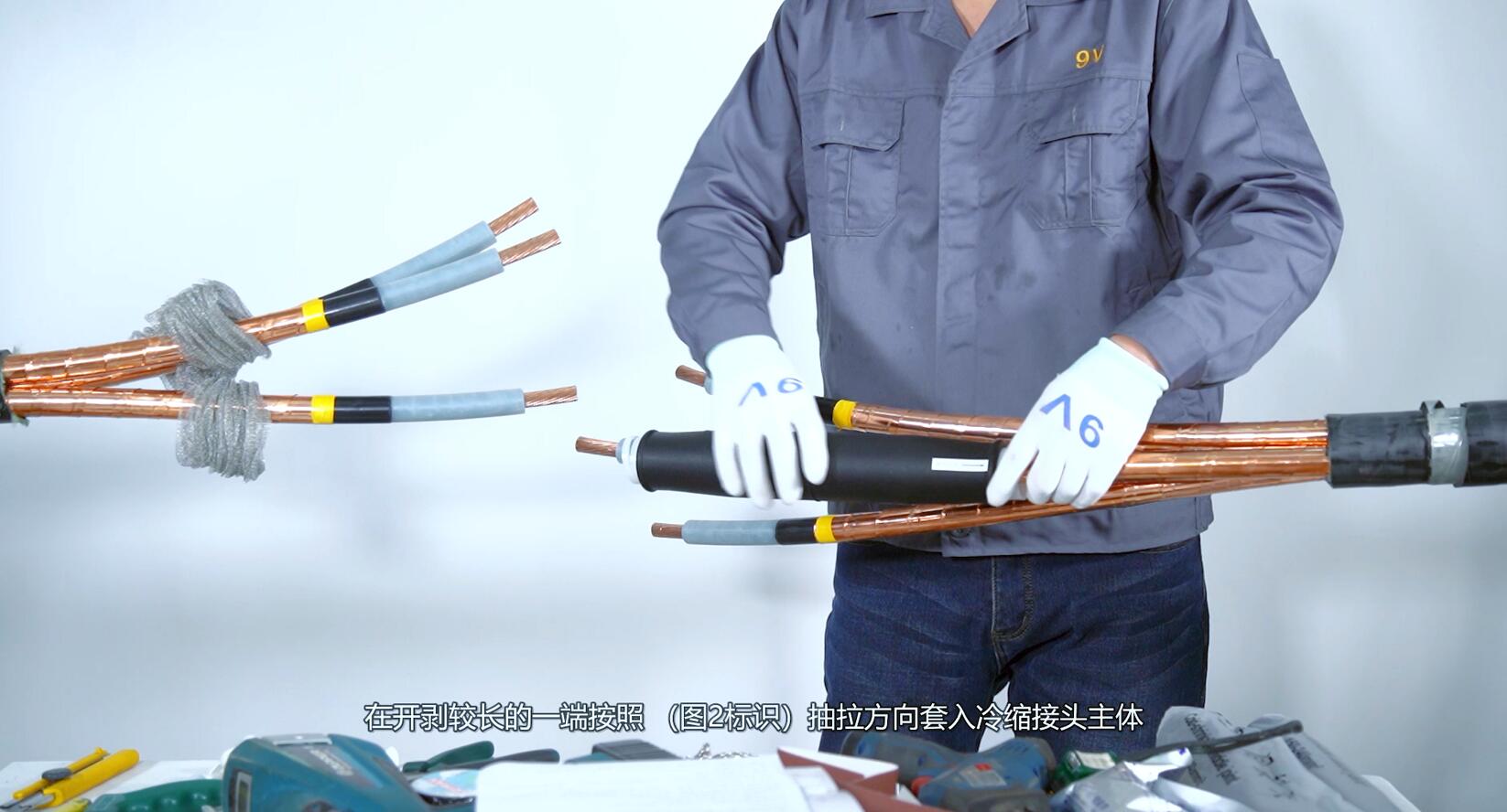
i: Insert the copper mesh at the shorter end of the strip, and insert the body of the cold shrink joint at the longer end of the strip according to the drawing direction (marked in Figure 2).
3. Install the connecting pipe
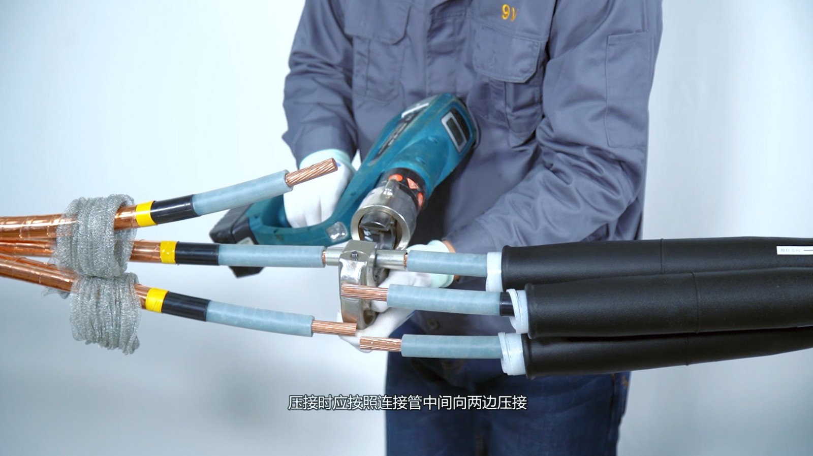
a: Sleeve into the connecting pipe and perform crimping. When crimping, it should be crimped to both sides according to the middle of the connecting pipe.
b: After the crimping is completed, file the edges and corners and burrs on the connecting pipe and clean the connecting pipe.
c: Measure the size between the insulation ports, find the center point and measure the 300mm positioning calibration point from the center point to the shorter end of the strip and mark it.
4. Install the cold shrink body
a: Clean the surface of the insulating layer with cleaning paper, and apply silicone grease evenly after the cleaning agent is dry.
b: Measure 15mm back from the semi-conductive layer incision and make a mark as the shrinkage positioning point of the cold shrink body.
c: Align the main body joint with the shrinkage positioning point, remove the support bar to shrink the main body, and immediately calibrate the distance from the center point of the main body joint to the dimensional calibration point after the joint shrinkage is greater than 50%.
d: Wipe off the overflowing silicone grease at both ends.
e: The semi-conductive layer at both ends of the intermediate joint is polished and cleaned with fine sandpaper and then wrapped with waterproof tape.
f: Pull out the copper mesh and completely cover it on the installed joint body.
g: Fix the ground wire together with the copper mesh on the copper shielding layer with a constant force spring, and wrap the PVC tape around the constant force spring.
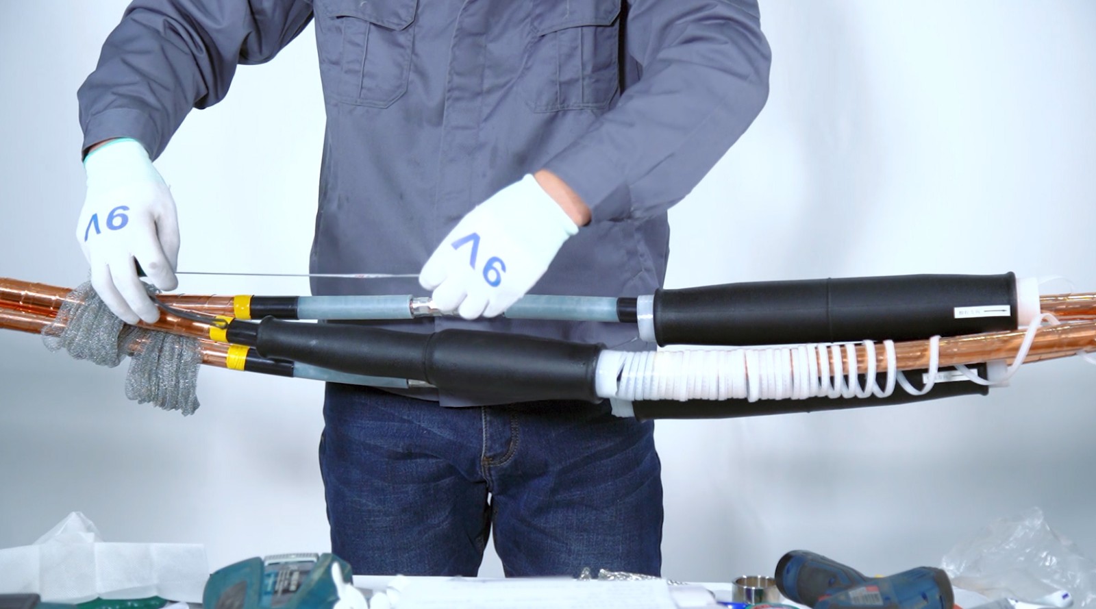
5. Waterproof sealing treatment
a: The three phases are arranged close together, the filler is restored, fixed with PVC tape, and then wrapped around the whole in a semi-lapped manner with wide PVC tape.
b: Wrap the waterproof tape around the inner sheath of the cable, and wrap the waterproof tape in a half-lap from one end of the inner sheath to the inner sheath at the other end.
c: Connect the steel armor at both ends of the cable with a ground wire and fix it with a constant force spring, and wrap the PVC tape around the constant force spring.
d: Wrap it with PVC tape to make the ground wire close to the inner waterproof tape.
e: Wrap filler glue around the outer sheath of the cable and the constant force spring to fill the gap.
f: Wrap the waterproof tape from one end of the outer sheath to the other end of the outer sheath, and overlap with the outer sheaths at both ends by 60mm respectively. The winding direction should be opposite to that of the inner waterproof tape.
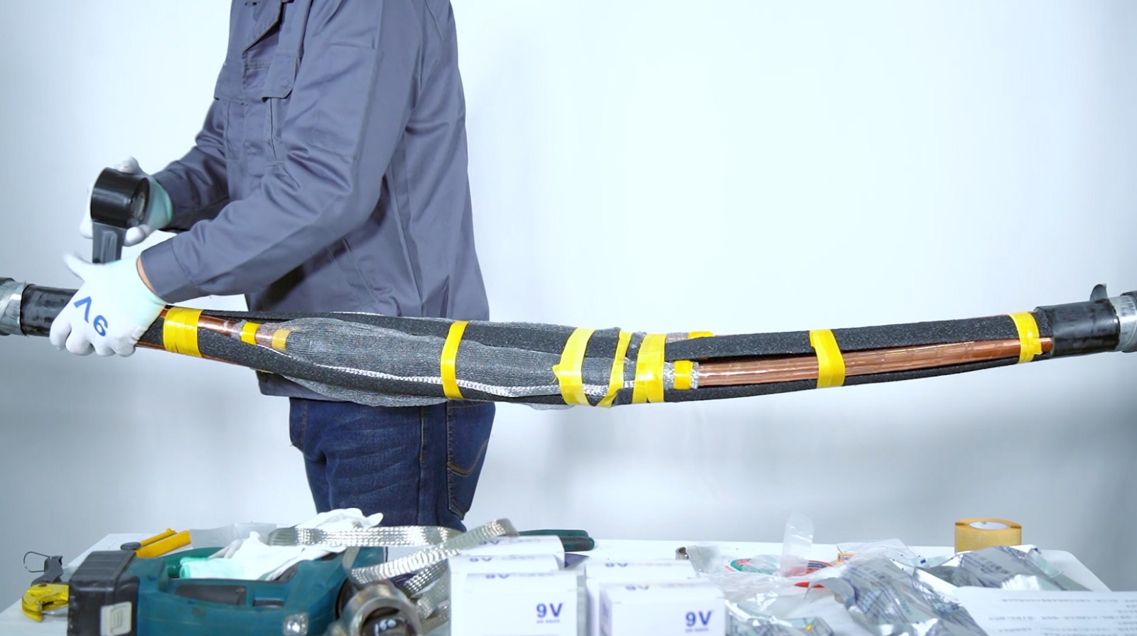
6. Install the armor belt
a: Wrap the armor tape in a semi-lapped way, exceeding the waterproof tape by 50-100mm. (Action soaked in water)
b: Fix the end armor belt with pvc.
c: Move the cable after the armor tape is cured.
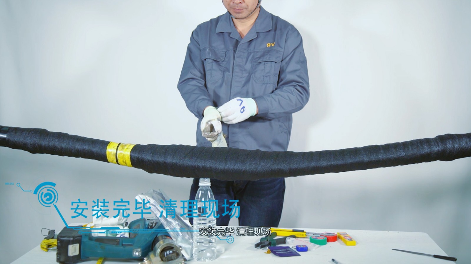
7. Installation finish, clean up the site.
Please watch the full video:
Hotline: +86 18001554818 / +86 18068406516


